The Pixel Before the Flat Screen
The pixel before the flat screen was not a fixed square. Learn how CRT scanning and panel grids shape image detail and the way pixels are understood.
The most common mistake in thinking about a pixel before the flat screen is to picture a tiny square fixed on the glass. In a CRT, the image appeared as a moving electron beam swept across phosphor, but its timing and signal could still represent discrete image samples. Knowing the difference helps explain what changed—and what did not—when flat panels became common.
A CRT formed images with a scanned beam
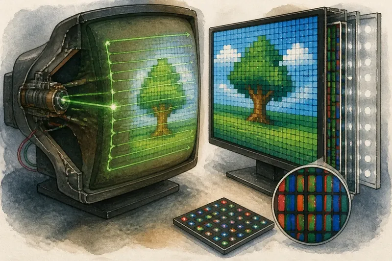
A cathode-ray tube, or CRT, sent electrons from an electron gun towards a phosphor-coated screen. Magnetic fields steered the beam across the face, line by line, while the picture signal varied its intensity. The struck phosphor emitted visible light.
The screen did not contain a neat grid of individually wired picture cells. Instead, the beam revisited positions in a repeating raster. Digital image information could be organised into samples, and the display’s timing could represent those samples as the beam moved; the samples did not have to correspond to sharply bounded squares on the glass.
The beam had a finite spot, and the phosphor had its own pattern and texture. A sample could therefore influence a small area rather than one cleanly separated point. The visible detail depended on the signal, scan timing, beam focus and phosphor together.
The raster gave CRT images a regular structure
Although the glowing spot moved continuously, the picture followed a regular sequence of horizontal lines. Timing cues kept the sweep aligned, and the signal determined how brightly the beam lit the phosphor as it travelled. This raster provided a consistent way to place image information without a physical cell for every sample.
Digital graphics made the pixel a useful name for an image sample arranged in rows and columns. A CRT could render such data, but it did not simply reveal a matching mosaic. The display translated the ordered information into a timed beam, and the beam’s spot and the phosphor’s response softened some boundaries.
Fine lines on a CRT could shimmer or look soft, while curves could appear less sharply stepped. The result varied with the signal and the particular display; it does not mean the source image lacked pixels. It reflects a different route from image samples to emitted light.
Flat panels tied display locations to a fixed grid
In a typical LCD, rows and columns of picture elements form a stationary matrix. Each pixel location contains red, green and blue subpixels, while liquid crystals control how much light from a backlight passes through colour filters.
The subpixels remain in place as the image changes. A controller updates their electrical state rather than sweeping a bright spot across the screen. That fixed grid makes it natural to describe a panel pixel as an addressable location, though it is still useful to distinguish that hardware location from a sample in an image file.
When an image’s sample grid aligns with the panel grid, image information can map directly to corresponding locations. When the grids differ, the display or software scales the image, assigning its samples across the available panel locations.
A panel pixel is not always a simple square of colour
“Pixel” can mean an image sample, an addressable location in a display matrix, or the group of coloured subpixels that produces a perceived colour. These meanings often correspond closely, but they are not identical.
Many LCDs use separate red, green and blue subpixels at each pixel location. Their combined light produces the colour seen there. Physical layouts vary, so the subpixels are not always arranged as identical stripes.
OLED panels add a different light-producing mechanism: their elements emit light directly rather than modulating a separate backlight. They still use an addressable matrix, but their arrangements of emitting elements can differ from the familiar LCD pattern. The pixel remains a useful image location, even when its physical construction changes.
Scaling shows which pixels belong to the image and the screen
Say you open a small pixel-art illustration on a laptop with a denser panel grid. If the software enlarges each image sample into crisp blocks, the artwork keeps its stepped edges; if it smooths the enlargement, neighbouring colours blend and those edges look softer. The illustration gains screen area, not new detail.
Scaling determines how existing image samples map onto the panel’s fixed locations. Photographs and video often benefit from transitions that look natural, while diagrams, small text and pixel art may need crisp edges. The suitable setting depends on the content and how it will be viewed.
What does “pixel” mean on a CRT?
Was a CRT pixel a physical dot?
Not in the same sense as a fixed cell on a flat panel. A CRT created image positions by timing and steering its beam across phosphor, rather than addressing a permanent square on the screen.
Did CRT pictures have a resolution?
They had practical limits on visible detail, shaped by the signal, scan pattern, beam focus and phosphor. Those limits do not reduce neatly to a count of independent physical pixels, because a CRT did not form its picture from a fixed matrix of cells.
Why can CRT graphics look soft or rounded?
The beam spot and phosphor response spread light across small areas, which can blend neighbouring image samples. The effect varies with the tube and signal, but it can soften sharp edges and make curves look less jagged.
Is a pixel the same as a subpixel?
Usually, a panel pixel is a colour location made from multiple subpixels, often red, green and blue. A subpixel is one part of that location, not a complete full-colour image sample on its own.
The useful distinction is between image samples and display locations
When comparing screens, separate the pixel grid in the content from the physical grid in the panel. A photograph, video frame or drawing has image samples arranged in rows and columns; a panel’s pixels and subpixels determine how those samples can be rendered.
A CRT connected the two through a timed scan, while a flat panel used a stationary matrix. That contrast is useful, as long as it is not taken to mean that CRT signals had no discrete timing or sample structure. The pixel before the flat screen was not simply absent: its relation to the hardware was different.
For a practical comparison, look at a high-contrast edge on both kinds of display if you have access to them. A CRT may show a soft edge shaped by its beam and phosphor, while a flat panel may show the edge aligned with its fixed grid or altered by scaling. That distinction—between image samples and the way a display renders them—remains a useful way to understand what a pixel means.